The Paper Tesla Scribbled in Pencil: How AC Won
The 1894 File · No. 7 of 12. Every quote below is cited from the first edition, page numbers included.
Published: October 18, 2026 | Updated: October 18, 2026
Standfirst. Nikola Tesla's alternating-current motor is usually retold as a flash of genius in a park in 1882. The paper that made the system public is a smaller and more interesting story. The editor of the 1894 book had to talk Tesla into giving a paper at all, the paper was written in pencil the night before the meeting, and the book that reprints it also prints the test numbers: 50 per cent in 1888, nearly 90 per cent by 1889, 94 and 95 per cent on the larger machines.
The Man Who Had to Beg Him
The 1894 volume is usually described as a book by Tesla. Large parts of it were written about him by T. C. Martin, the editor of The Electrical Engineer, and Martin tells us how one of the most important documents in the book arrived. He notes that he was at the time the chairman of the Institute Committee on Papers and Meetings, and that he "had great difficulty in inducing Mr. Tesla to give the Institute any paper at all" (1894, p. 9). Tesla, he writes, "was overworked and ill, and manifested the greatest reluctance to an exhibition of his motors, but his objections were at last overcome" (1894, p. 9).
Then the line that makes the episode worth telling: "The paper was written the night previous to the meeting, in pencil, very hastily, and under the pressure just mentioned" (1894, p. 9).
The paper was "A New System of Alternate Current Motors and Transformers", read before the American Institute of Electrical Engineers in New York in May 1888 (1894, p. 9). Its subject is the machine that runs most of the world now. And the same month the paper was read, the patent for it was granted: US patent 381,968, 'Electro-Magnetic Motor', filed 12 October 1887, issued 1 May 1888 (patent record).
Haste in the writing did not mean haste in the work. Martin adds a warning that most retellings skip: "Mr. Tesla made no attempt in that paper to describe all his work" (1894, p. 9). The paper is a slice, deliberately small, of a polyphase system that was already under patent and already being built.
What the Paper Actually Argued
Tesla does not open with a vision. He opens with an audit of the competing system, and the audit is mechanical. A dynamo, he points out, makes alternating current and then forces it through a commutator, "a complicated device and, it may be justly said, the source of most of the troubles experienced in the operation of the machines" (1894, p. 10). The motor then has to undo the same trick. His conclusion is blunt: "In reality, therefore, all machines are alternate current machines, the currents appearing as continuous only in the external circuit" (1894, p. 10).
From that he draws the design rule. Direct current is only worth having if you actually generate and consume it as direct current, and "the employment of continuous currents would only be justified if we had dynamos which would primarily generate, and motors which would be directly actuated by, such currents" (1894, p. 10). We do not. So the commutator is work being done for no reason, twice.
Strip out both commutators and one problem is left, and he states it as the question the paper exists to answer: how to shift the poles of a motor progressively "by the direct action of alternate currents" (1894, p. 11). That is the whole invention in one sentence. Everything after it is the answer.
The Idea, in One Paragraph
Take a ring wound with iron plates. Put two separate coils on it, at right angles to each other, and run them back to a generator whose armature carries two coils at right angles too (1894, p. 11). Now turn the generator.
Because the two circuits reach their peaks at different moments, the ring is never simply magnetised harder and softer. Its north and south poles move around the iron. The book walks through it in eight diagrams, one step per eighth of a turn, and states the result plainly: "during one revolution of the armature the poles of the ring are shifted once around its periphery, and, each revolution producing like effects, a rapid whirling of the poles in harmony with the rotation of the armature is the result" (1894, p. 13). Reverse one circuit and the travel reverses (1894, p. 13). Use three wires instead of four and it works the same, "one forming a common return for both circuits" (1894, p. 14).
Bring a light steel disc near the ring on a fine pivot and it spins. The explanation given is a tangential pull: each approaching pole induces the opposite pole in the nearest point of the disc, and "as the pole is shifted further away from the disc a tangential pull is exerted upon the same, and the action being constantly repeated, a more or less rapid rotation of the disc is the result" (1894, p. 14). The effect depends on how slowly iron magnetises, which is why "a disc of hard steel is much more affected than a disc of soft iron" (1894, p. 14).
To prove the ring and a spinning magnet are the same thing, Tesla did the obvious experiment: he rotated a strong electromagnet by mechanical power and got "phenomena identical in every particular to those mentioned above" (1894, p. 15). Iron filings on paper over the ring show "a magnetic whirl" (1894, p. 15). A field that travels in a circle is not a metaphor. It is a thing you can put filings on.
Two Motors: One That Locks, One That Chases
From the travelling field, the paper says, two typical forms of motor follow. The first has "a comparatively small rotary effort at the start but maintaining a perfectly uniform speed at all loads, which motor has been termed synchronous". The second has "a great rotary effort at the start, the speed being dependent on the load" (1894, p. 16).
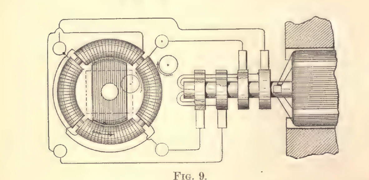
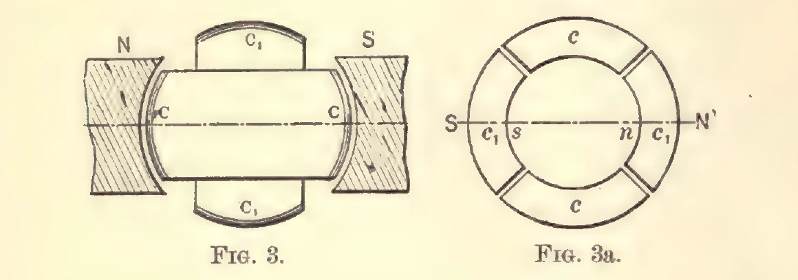
The synchronous motor is a slotted iron disc inside that ring. The book says the disc will "closely follow the movement of the poles" and will "maintain exactly the same speed at all loads within the limits of its capacity" (1894, p. 17). Its speed is set by the pole count, not by the load, and the paper shows how to build a whole system around that: a generator with many poles at the supply station, motors of the synchronous type at the far end, each with "a greater number of pole projections or coils, the number being preferably a multiple of two and three", so that rewiring one motor changes its speed (1894, p. 23). He also notes that "Any of the dynamos at present in use may be easily adapted for this purpose" (1894, p. 22). That is why the system could be bolted onto the machines factories already had.
The other motor is the one that matters more, and Fig. 14 is its armature. Tesla put "within the ring a properly subdivided cylindrical iron core wound with several independent coils closed upon themselves", and says "Two coils at right angles as in Fig. 14, are sufficient" (1894, p. 20). Nothing feeds those coils. The travelling field induces current in them, and the induced poles sit at right angles to the field's, so the pull never stops: "a continuous pull is exerted upon the periphery of the armature" (1894, p. 20).
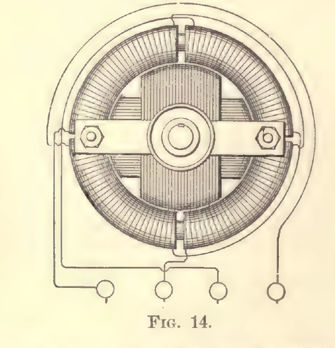
That is an induction motor, drawn and explained in 1888 language. The paper is candid about what it does: "It will be found that the rotary effort in these motors fully equals that of the continuous current motors" (1894, p. 21). Run light, it runs almost at field speed (1894, p. 21). Add load and it slows, draws more current, and gives more torque. Reverse the field and it brakes and reverses, so fast that "the reversal is instantaneous" (1894, p. 22). Pole projections, he warns, "diminish the torque and produce a tendency to synchronism" (1894, p. 21). That trade-off is still in every textbook.
The Efficiency Climb, in Public
The book does not ask you to take any of this on faith, because it prints the test record.
- May 1888. Prof. Anthony, addressing the American Institute of Electrical Engineers about
two small motors he had tested, reported that one "gave an efficiency of about 50 per cent, and the other a little over sixty per cent" (1894, p. 8).
- 1889. Tests reported from Pittsburgh, "made by Mr. Tesla and Mr. Albert Schmid, on motors
up to 10 H. p. and weighing about 850 pounds", gave machines at "an efficiency of nearly 90 per cent" (1894, p. 8).
- Larger machines on the three-wire system: it "was then found practicable to obtain an
efficiency, with the three wire system, up to as high as 94 and 95 per cent" (1894, p. 8).
Martin says why he lists them: the figures are "cited to show that the efficiency of the system has not had to wait until the present late day for any demonstration of its commercial usefulness" (1894, p. 8). Tesla, in the paper itself, claims as much for the design: "At full loads the motors show an efficiency fully equal to that of the continuous current motors" (1894, p. 24).
Read the three numbers as a schedule rather than a boast. Half efficiency in a college laboratory in 1888. Ninety per cent on a ten-horsepower machine in 1889, and 850 pounds of iron and copper to get there. Ninety-four on the biggest machines. That is five years of shop work: laminated cores, drawn wire, bolted frames, a prony brake and a stopwatch.
What the Internet Gets Wrong
That the phrase 'magnetic generator' belongs to this story. It does not appear in the 1894 book as a name for anything Tesla built. A word search of our copy of the text finds the string only inside "pyro-magnetic generator", which is a heat-driven device discussed in a different chapter (1894, pp. 6, 429), plus the index entry for it (1894, p. 496). What the book does contain is an induction motor and a transformer system, with the armature coils closed on themselves (1894, p. 20), and a model described in the same volume as "a twophase motor, as well as an induction motor and transformer" (1894, p. 479).
That the pencil paper was the whole invention. The editor says it was not: "Mr. Tesla made no attempt in that paper to describe all his work" (1894, p. 9). The paper covers the rotating field, motors with closed conductors, synchronising motors and rotating-field transformers, and stops there (1894, p. 9).
That a rotating field is subtle. Two coils, out of step, and the poles walk around the ring. Tesla's own demonstration apparatus was a pivoted steel disc and some iron filings (1894, p. 14). The subtlety is not in the idea. It is in making iron, copper and a generator behave at scale, which is exactly what the 1889 figures are about.
If You Came Here for a Motor to Build
The honest transfer from this chapter to a workbench is a warning about sequence. A rotating field needs more than one circuit out of step, and the machines that reached 90 per cent were wound, laminated and measured in a shop. If you are evaluating a permanent magnet design at home, the useful comparisons are the ones that talk about windings and load: how a dynamo generator actually puts out current, what the plans cost and what they claim, and whether a Tesla magnetic generator is worth it.
For what the same system looked like when it was industrial, see Tesla's 1893 World's Fair exhibit, where one of these rings stood on a table with a bar magnet beside it to prove the point. For the high-frequency end of the same family of machines, and the numbers Tesla reached there, see 30,000 alternations a second.
Frequently Asked Questions
What Is a Rotating Magnetic Field, in Plain Terms?
Two or more coils arranged around a ring, fed by alternating currents that reach their peaks at different moments. The combined magnetism points in a direction that turns instead of just getting stronger and weaker. The 1894 book describes the result exactly: 'during one revolution of the armature the poles of the ring are shifted once around its periphery, and, each revolution producing like effects, a rapid whirling of the poles in harmony with the rotation of the armature is the result' (p. 13). Swap the connections of one circuit and the field turns the other way (p. 13).
Why Does an Induction Motor Need No Brushes or Commutator?
Because the current in the moving part is induced, not fed to it through contacts. The book states the principle in one sentence: 'the rotation of the poles produces corresponding inductive effects and may be utilized to generate currents in a closed conductor placed within the influence of the poles' (p. 15). Tesla's argument for dropping the commutator is in the same paper: it is 'the source of most of the troubles experienced in the operation of the machines' (p. 10).
How Efficient Were the First Alternating Current Motors?
The 1894 volume prints the record. In May 1888 Prof. Anthony told the American Institute of Electrical Engineers that of two small Tesla motors he had tested, one 'gave an efficiency of about 50 per cent, and the other a little over sixty per cent'. In 1889 tests from Pittsburgh 'made by Mr. Tesla and Mr. Albert Schmid, on motors up to 10 H. p. and weighing about 850 pounds' showed 'an efficiency of nearly 90 per cent', and with larger machines on the three-wire system it was found practicable to obtain efficiency 'up to as high as 94 and 95 per cent' (1894, p. 8).
Did Tesla Invent the Rotating Magnetic Field?
The 1894 book does not argue priority; it presents the May 1888 paper as one part of a larger body of work that Tesla declined to describe, and its editor notes that 'Mr. Tesla made no attempt in that paper to describe all his work' (p. 9). The machine itself is patented: US patent 381,968, 'Electro-Magnetic Motor', filed 12 October 1887 and granted 1 May 1888, which describes passing alternating currents through independent circuits to shift the poles progressively. Anyone writing a history of the induction motor has to deal with more than this one paper; anyone citing this one paper can say what it contains and what it measured.
Those 1888 machines were built by a shop with laminated iron, drawn wire and a test bench, and their efficiency took years to climb. If you want the honest version of a home generator, the plans we recommend come with a parts list and a straight answer about output.
We earn a commission if you buy through that link. It does not change what the 1894 book says.
Sources
- The Inventions, Researches and Writings of Nikola Tesla, ed. Thomas Commerford Martin. New York: D. Van Nostrand, 1894 (entered 1893). Scan: archive.org item inventionsresear00martiala. Public domain.
- Chapter III, 'The Tesla Rotating Magnetic Field. Motors with Closed Conductors. Synchronizing Motors. Rotating Field Transformers', printed pp. 9 to 25 of the 1894 edition
- The editor's note on how the paper came to be written, and the efficiency figures from Anthony's 1888 remarks and the 1889 Pittsburgh tests, printed p. 8 and p. 9 of the 1894 edition
- US patent 381,968, "Electro-Magnetic Motor", Nikola Tesla, filed 12 Oct 1887, issued 1 May 1888
- Chapter XLII, on the same class of machine as an exhibit at the 1893 World's Fair, printed p. 479 of the 1894 edition
- Pages of the 1894 edition used here: p. 8, p. 9, p. 10, p. 11, p. 12, p. 13, p. 14, p. 15, p. 16, p. 17, p. 18, p. 20, p. 21, p. 22, p. 23, p. 24, p. 25, p. 479