30,000 Alternations a Second: Tesla's Lost Generator
The 1894 File · No. 11 of 12. Every quote below is cited from the first edition, page numbers included.
Published: October 17, 2026 | Updated: October 17, 2026
Standfirst. Ask what Nikola Tesla's high-frequency machines actually were and you usually get a coil and a guessed number. The 1894 volume has something better: a detailed description of rotary alternators with hundreds of iron poles, the speeds they were run at, the currents they gave, and a list of the ways they failed. Chapter XXIX runs from p. 374 to p. 391 and it is the most engineering-dense material in the book.
The Problem Was a Noisy Lamp
The chapter opens with an objection to alternating current, not with a boast. Arc lamps run on alternating or pulsating currents "emit a pronounced sound, varying with the rate of the alternations or pulsations of current", and the book explains why: the noise comes from "the rapidly alternating heating and cooling, and consequent expansion and contraction, of the gaseous matter forming the arc" (1894, p. 374). Worse, the arc's resistance rises periodically, which makes small arcs impossible: "small arcs are impracticable" (1894, p. 374).
Tesla's answer was to go up in frequency until the problem stopped being audible. Push the rate of change past the limit of hearing and "the sound produced by or in the arc becomes practically inaudible" (1894, p. 376). Fast alternation also keeps the arc hot, and a hot arc has low resistance, so it stays lit. High-frequency arcs, the chapter says, "possess the advantages of silence and persistency" (1894, p. 374).
That is the commercial reason for the whole chapter. Not mystery, a hum.
The Machine: An Annulus With Hundreds of Poles
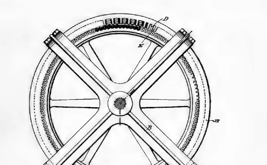
The design is in Figs. 199 and 200. "A is an annular magnetic frame, the interior of which is provided with a large number of pole-pieces D" (1894, p. 375). Because the poles are small and close together, you cannot wind a coil around each one. Instead the field is wound with a single insulated conductor run "zigzag through the grooves", around and around the ring until there are as many layers as you want, which leaves the poles energised with alternately opposite polarity all the way round (1894, p. 375).
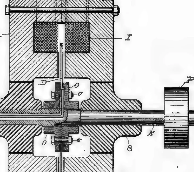
The armature is a spider carrying a ring, turned down into a trough and packed with "a mass of fine annealed iron wires", with pins set in the sides of the ring and the armature coils wound over the periphery around those pins. The coils are connected in series and their terminals are carried out through a hollow shaft to contact rings, where brushes take the current off (1894, p. 375).
The point of all that fiddly construction is one sentence: "In this way a machine with a very large number of poles may be constructed" (1894, p. 375). Frequency out of a rotating machine is poles times revolutions. If you cannot spin it faster, you add poles.
The Numbers, As the Book Gives Them
This is the part most retellings leave out, and it is the reason the machine is worth writing about.
- Three hundred and seventy-five to four hundred poles, driven "at a speed of fifteen
hundred or sixteen hundred revolutions per minute, which will produce ten thousand or eleven thousand alternations of current per second" (1894, pp. 375, 376).
- A specific experimental machine with a wrought-iron field ring 32 inches outside
diameter, 30 inches inside, carrying "384 polar projections" and 384 coils in two series. It was run "as high as 3,000 revolutions per minute" and gave "as high as 10 amperes" (1894, p. 377).
- The limit of the simpler field design: "Up to about 15,000 alternations per second in an
experimental machine, the former plan may be followed, but a more efficient machine is obtained on the second plan" (1894, p. 376).
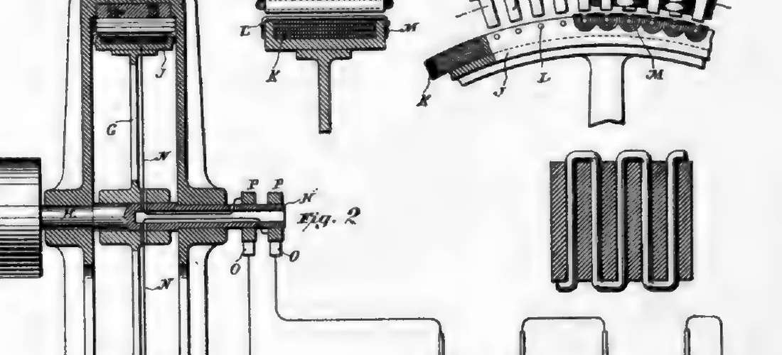
- The second plan, shown in Fig. 206: "the field had 480 polar projections on each side,
and from this machine it was possible to obtain 30,000 alternations per second" (1894, p. 381).
Thirty thousand alternations a second, out of a shaft with a belt pulley on it, described in a book published in 1894. That is a real figure from a real book, and it beats anything the myth needs.
What the Frequency Bought Him
The chapter's payoff is an experiment you could almost do in a garage, if you had a 20,000-alternation generator.
"A machine was used giving about 20,000 alternations per second. Two bare wires about twenty feet long and two millimetres in diameter, in close proximity to each other, were connected to the terminals of the machine at the one end, and to a condenser at the other" (1894, p. 391). With a small air-core transformer and a Cardew voltmeter, the electromotive force read about 120 volts at the condenser and about 65 volts at the machine, falling "inch by inch" along the wires. The writer's conclusion is honest rather than triumphant: "The writer looked for a case of resonance, but he was unable to augment the effect by varying the capacity very carefully and gradually or by changing the speed of the machine. A case of pure resonance he was unable to obtain" (1894, p. 391).
In a lecture printed earlier in the same volume, Tesla puts the same capability the other way: at "a few thousand volts there is no particular difficulty encountered in conveying currents from a machine giving, say, 20,000 alternations per second, to quite a distance", and then adds the caveat that matters, "This number of alternations, however, is by far too small for many purposes, though quite sufficient for some practical applications" (1894, p. 151).
What he then did with a line like that on one conductor only, and why the return path in those demonstrations was the room rather than a second wire, is worked through on its own page at Tesla's One-Wire Power: The Experiment Textbooks Skip, which quotes the same volume's arithmetic for why one wire was the economical choice at high frequency (1894, p. 267).
"A tale of woe": Why the Machine Was Hard
Martin reprints Tesla writing in the Electrical World in February 1891 about building these generators, and it is funny because it is exact. Anyone attempting such a machine for the first time "will have a tale of woe to tell". He starts, naturally, by making an armature with the required number of poles, and gets "an apparatus which is fit to accompany a thoroughly Wagnerian opera", one that may "possess the virtue of converting mechanical energy into heat in a nearly perfect manner" (1894, p. 381).
The heat is the story. Iron at high frequency is a heater unless you build it out of lamination and thin wire: "As the polar projections must necessarily be very narrow, very thin wires or sheets must be used to avoid the eddy current effects" (1894, p. 381). In the 384-pole machine "it was found impracticable to use any wire much thicker than No. 26 B. and S. gauge on account of the local effects" (1894, p. 377). The armature wires had to be wound with care "as they are apt to fly off in consequence of the great peripheral speed" (1894, p. 377). Insulation was its own problem: with a gas present, discharge can work "through as much as an inch of the best solid insulating material" (1894, p. 151).
The chapter ends by naming what Tesla hoped would replace these machines: the oscillator, which its inventor believed would give "the necessary high frequency conditions, while relieving him of the inconveniences that attach to generators of the type described at the beginning of this chapter" (1894, p. 391). That machine has its own record, and its own afterlife as a legend: the earthquake machine, from the 1893 documents. The exhibit where both were shown is here.
What the Internet Gets Wrong
A single "Tesla coil frequency". There isn't one. The rotary machines in this chapter run from a few thousand to 30,000 alternations per second depending on poles and speed, and Tesla calls 20,000 too small for many purposes (1894, p. 151). A page that quotes one number for "a Tesla coil" is describing a circuit, not a machine, and usually guessing.
That high frequency was always about wireless power. In this chapter it is about arc lamps: silence, and the ability to run a small arc (1894, p. 374). The wireless material is elsewhere in the book, and it comes later.
That the machine was a curiosity. It ran "Mr. Tesla's laboratory lights" and was "capable of running two arcs of normal candle power" (1894, pp. 377, 376). It was a working laboratory supply.
That the captions in this book can be trusted. Our own extraction tool read the caption under Fig. 199 as "Fig. 203", and the one under Fig. 206 as "Fig. 207". Both printed pages say otherwise, and we re-cropped from the scans to get the right plates. Every figure on this page was checked against the page it came from.
If You Came Here for a Generator to Build
The honest read of Chapter XXIX is that frequency was expensive: more poles, thinner wire, tighter clearances, careful winding, and a machine that hums and heats if you get it wrong. Nothing in it supports a claim that a home-built magnet machine can skip that work. These are alternators; the motors that made the same polyphase system useful, and the measured efficiency record that goes with them, are in the paper Tesla scribbled in pencil. If you want the practical version of this subject, read what a magnetic generator actually costs and how a dynamo generator is put together.
Frequently Asked Questions
What Frequency Did Tesla's Alternators Reach?
The 1894 book gives three figures. A machine with 375 to 400 poles driven at 1,500 to 1,600 revolutions per minute produces 'ten thousand or eleven thousand alternations of current per second' (p. 375). Up to 'about 15,000 alternations per second' the simpler field design could be used (p. 376). A later machine with '480 polar projections on each side' could be made to give 30,000 alternations per second (p. 381).
Why Did Tesla Want High Frequency in the First Place?
To run arc lamps quietly and small. The book explains that alternating-current arcs 'emit a pronounced sound' because the gas in the arc heats and cools at the rate of the alternations, and that at low frequency 'small arcs are impracticable'. Currents of high enough frequency gave arcs that had 'the advantages of silence and persistency' (1894, p. 374).
Is a Tesla Coil the Same As a High-Frequency Alternator?
No. A Tesla coil is a transformer driven by interrupted or oscillating current; the machines in Chapter XXIX are rotary generators with hundreds of iron poles. The book's own numbers for the rotary machines run to 30,000 alternations per second, and Tesla says in a lecture that 20,000 was 'by far too small for many purposes, though quite sufficient for some practical applications' (1894, p. 151). Any single 'Tesla coil frequency' you are given is a simplification.
Why Did This Type of Generator Disappear?
The book records the reasons without editorialising. Eddy currents forced 'very thin wires or sheets' (p. 381); in one machine it was 'impracticable to use any wire much thicker than No. 26 B. and S. gauge' (p. 377); the armature wires were 'apt to fly off in consequence of the great peripheral speed' (p. 377). The chapter closes by pointing to the Tesla oscillator as the intended replacement (p. 391), and that machine was superseded too.
A machine that makes 30,000 alternations a second is an engineering achievement, not a shortcut. If someone is selling you a generator that skips the engineering, the plans we recommend come with a parts list and a straight answer about output.
We earn a commission if you buy through that link. It does not change what the 1894 book says.
Sources
- The Inventions, Researches and Writings of Nikola Tesla, ed. Thomas Commerford Martin. New York: D. Van Nostrand, 1894 (entered 1893). Scan: archive.org item inventionsresear00martiala. Public domain.
- Chapter XXIX, 'Tesla Alternating Current Generators for High Frequency, in Detail', printed pp. 374 to 391 of the 1894 edition
- Tesla's own account of building these machines, reprinted by Martin from the Electrical World, February 1891 (1894, p. 381)
- Wikipedia, "Tesla's oscillator", on the supersession of reciprocating and rotary high-frequency generators (secondary source, checked 2026-10-10)
- Pages of the 1894 edition used here: p. 151, p. 374, p. 375, p. 376, p. 377, p. 381, p. 391