Tesla's 1893 World's Fair Exhibit, Walked Through
The 1894 File · No. 9 of 12. Every quote below is cited from the first edition, page numbers included.
Published: October 16, 2026 | Updated: October 16, 2026
Standfirst. Nikola Tesla had a table of motors at the 1893 World's Fair in Chicago, and a man who was there wrote it down. Chapter XLII of the 1894 volume is a guided tour of that table: what stood where, what each machine did, and which of them had already been tested by a professor in 1888. It is a better document than any photograph of the Fair, because it explains the hardware.
Where the Table Stood
The exhibit was not a pavilion. Tesla's apparatus "occupied part of the space of the Westinghouse Company, in Electricity Building" (1894, p. 477). The chapter's author is Thomas Commerford Martin, editor of The Electrical Engineer and a past-president of the American Institute of Electrical Engineers, and he is writing as someone who arranged the exhibit rather than as someone visiting it.
He gives the reason for the display before he describes it. The commercial stands showed "the state of the art"; the personal exhibits showed "the work of the individual inventor, which lies at the foundation of much, if not all, industrial or mechanical achievement" (1894, p. 477). Tesla's table was there to show a line of development, and the chapter follows that line object by object.
The Big Ring, and a Magnet on Bearings
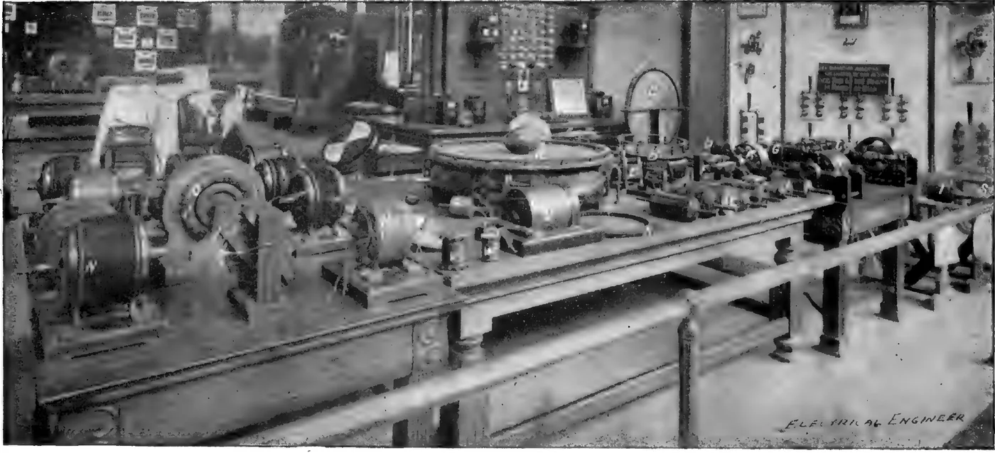
The first thing the photograph picks out, labelled A, is a large ring. Its purpose is to make a rotating magnetic field visible: the field "was very powerful and exhibited striking effects, revolving copper balls and eggs and bodies of various shapes at considerable distances and at great speeds" (1894, p. 477). It was wound for two-phase circuits, and the winding was spread so the field came out nearly uniform. Martin credits the build to "Mr. C. F. Scott, electrician of the Westinghouse Electric and Manufacturing Company" (1894, p. 477). A smaller ring, at B, was built to show an armature turning inside that field.
Next to the rings sat a bar magnet with a coil, mounted so it could turn in bearings. With it, the chapter says, Tesla "first demonstrated the identity between a rotating field and a rotating magnet" (1894, p. 479). That is the whole trick of an induction motor stated in one object: a field that travels in a circle and a magnet that travels in a circle are the same machine. If you want the paper that started it, the May 1888 AIEE paper is here.
One Model, Three Machines
The most interesting object on the table is at C, and the description is easy to skip because it sounds like a list of parts. It is "a two-phase motor, as well as an induction motor and transformer", built as a large outer ring of laminated iron carrying "two superimposed, separated windings which can be connected in a variety of ways" (1894, p. 479).
The induction-motor connection is the part worth stopping on. "When used as an induction motor, the current induced in one of the windings of the ring was passed through the other winding on the ring and so the motor operated with only two wires" (1894, p. 479). One winding is the transformer secondary; the same winding is then the supply to the other. Two wires in instead of four. This is not a trick that beats physics, it is a way of making one set of copper do two jobs, and it is exactly the kind of thing a home builder meets again when a machine is rewired for a different duty.
The Rest of the Table
The chapter keeps going, and the objects get stranger.
- At D, "one of the earliest rotating field motors": a thin iron ring with two sets of
coils, and an armature of steel discs partly cut away, mounted on a small arbor (1894, p. 479).
- At E, a motor used to regulate an arc lamp. Its two sets of coils were made different on
purpose: "one set being of German silver and the other of copper wire", so the two had different self-inductions (1894, p. 479).
- At F, a "magnetic lag motor". Alternating current magnetises the field projections and
the armature inside them the same way, and then "upon the cessation or reversal of the current the armature and field repel each other and rotation is produced in this way" (1894, p. 479).
- At G, a two-field motor with an armature in each field, both on one shaft. It also ran
backwards as a generator: "it has been used as a dynamo for the production of currents of any frequency between wide limits" (1894, p. 480). That sentence is the reason this exhibit matters to the high-frequency story; the machine behind Tesla's glowing tubes is here.
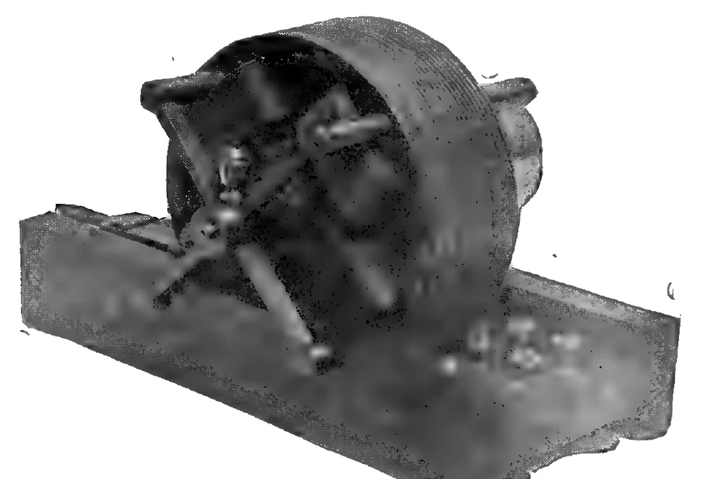
The machine in that photograph is at K on the table. Martin writes that it, and a second one shown in Fig. 299, had been shown at the AIEE lecture in May 1888, and that they were "the first rotating field motors which were independently tested" (1894, p. 481). They had been handed to Prof. Anthony for testing in the winter of 1887 and 1888, and the results, in Martin's words, were "quite satisfactory in every respect" (1894, p. 481). A machine on a museum table in 1893 was, five years earlier, a laboratory instrument that somebody else had measured.
The Armatures Were Photographed in 1888
Nine of the engravings in this chapter are close-ups of armatures, printed on p. 482 with their numbers running Fig. 300 to Fig. 310. Some are cylinders with bands of copper cast around iron discs; one is a block of soft steel with a coil closed on itself; another has holes under the surface with copper conductors embedded in them. The chapter says plainly that "the enlarged engravings are made from photographs taken early in 1888" (1894, p. 483).
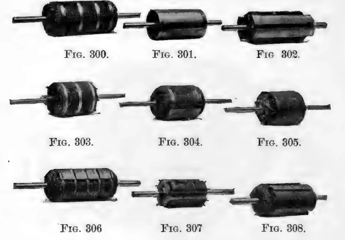
Martin does not pretend they all worked well. He writes that "each of these models involves some distinct idea and they all represent gradual development chiefly interesting as showing Mr. Tesla's efforts to adapt his system to the existing high frequencies" (1894, pp. 483, 484). That is an editor telling you that a table full of machines is a record of attempts, not a victory lap. It is also the most useful sentence in the chapter for anyone being sold a generator that supposedly needed no such years.
One caption here needs a warning of its own. When we ran optical character recognition over this page, the caption under the coil photograph on p. 484 came out as "FIG. 811." There is no Fig. 811 in a book whose illustrations stop in the 300s. The printed page says Fig. 311, and the text two pages on refers to "the small battery seen in Fig. 311" (1894, p. 485). We look at every crop before we use it for this reason.
What the Internet Gets Wrong
That Tesla Lit the Fair
The chapter does not say that, and it says something more specific: "the Westinghouse Company made a fine exhibit of the various commercial motors of the Tesla system, while the twelve generators in Machinery Hall were of the two-phase type constructed for distributing light and power" (1894, p. 485). Generation at the Fair was Westinghouse's plant. Tesla's exhibit was models.
That the Exhibit Was a Stunt
It was a lecture in hardware, and the dark room beside it was the part with the most show in it. Two large plates stood "at a distance of about eighteen feet from each other", and between them were tables of phosphorescent bulbs and tubes, some marked with names that would glow: "Helmholtz, Faraday, Maxwell, Henry, Franklin" (1894, p. 485). The same paragraph remembers "the greatest living poet of his own country, Zmaj Jovan", which is a detail no summary of the Fair seems to keep.
That Everything Ran at Full Power
It did not. The large coil "was operated at only a small fraction of its capacity, as the necessary condensers and transformers could not be had and as Mr. Tesla's stay was limited to one week" (1894, p. 485).
That the Oscillator Was a Later Invention
The chapter's last line about the exhibit is that Tesla also showed "some models of his oscillators" (1894, p. 485). That is the same machine as the earthquake story, told from the 1893 record rather than from 1935 memory.
If You Came Here for the Generator
Everything on that table needed a shop: laminated iron, brass bolts, wound coils, and a generator set to feed them. The efficiency figures from those same machines are in the 1888 paper section, and they took five years of industrial work to climb. If you want the honest version of the home version, start with building a magnetic generator or what the plans actually cost.
The exhibit itself was photographed for the book, and those photographs are on the page that catalogues the volume's illustrations one at a time, each cited to the printed page it sits on: Tesla 1894 Plates.
Those machines were built by a shop with tooling, and it took years to get them to 90 per cent. If you want the version of this that fits a home workshop, the plans we recommend come with a parts list and a straight answer about output.
We earn a commission if you buy through that link. It does not change what the 1894 book says.
Sources
- The Inventions, Researches and Writings of Nikola Tesla, ed. Thomas Commerford Martin. New York: D. Van Nostrand, 1894 (entered 1893). Scan: archive.org item inventionsresear00martiala. Public domain.
- Chapter XLII, 'Mr. Tesla's Personal Exhibit at the World's Fair', printed pp. 477 to 485 of the 1894 edition
- Pages of the 1894 edition used here: p. 477, p. 479, p. 480, p. 481, p. 482, p. 483, p. 484, p. 485